A capacitor is a type of electronic component that stores electrical charge. It consists of two conductive plates separated by an insulating material known as a dielectric. When a voltage is applied across the plates, an electric field is created, which causes the plates to accumulate a charge. This stored charge can then be discharged to provide a current in an electrical circuit.
Capacitors are commonly used in electronic circuits for a variety of purposes, such as filtering, smoothing, and decoupling. They are also used in applications where a sudden discharge of electrical energy is required, such as in power supplies, motor starters, and electronic flash units. Capacitors are available in a wide range of sizes, shapes, and capacitance values to suit different applications.
Units of Capacitance
The units of capacitance are the farad (F), microfarad (µF), and picofarad (pF). A farad is the standard unit of capacitance, named after the English physicist Michael Faraday. It is a very large unit, so capacitors are typically measured in microfarads or picofarads.
A microfarad is one millionth of a farad, and a picofarad is one trillionth of a farad. These units are commonly used to express the capacitance of small capacitors, such as those used in electronic circuits.
In addition to farads, microfarads, and picofarads, there are other units of capacitance that are used in certain applications. For example, the statfarad (statF) is a unit of capacitance used in the measurement of capacitors with very low capacitance values. The abfarad (abF) is a unit of capacitance used in the measurement of very large capacitors, such as those used in power transmission systems.
How to convert units of capacitance?
1 microfarad (µF) = 1000 picofarads (pF) 1 picofarad (pF) = 1000 nanofarads (nF)
For example, if you have a capacitor with a capacitance of 1000 pF, you can convert it to microfarads by dividing the value by 1000: 1000 pF / 1000 = 1 µF.
Similarly, if you have a capacitor with a capacitance of 1000 µF, you can convert it to picofarads by multiplying the value by 1000: 1000 µF x 1000 = 1,000,000 pF.
To convert from nanofarads to microfarads or picofarads, you can use the same conversion factors, but in reverse. For example, if you have a capacitor with a capacitance of 1000 nF, you can convert it to microfarads by dividing the value by 1,000,000: 1000 nF / 1,000,000 = 0.001 µF.
Types of capacitors
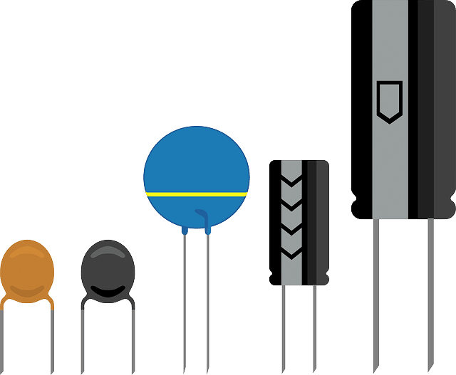
There are several types of capacitors, each with its own unique characteristics and applications. Some of the most common types of capacitors include:
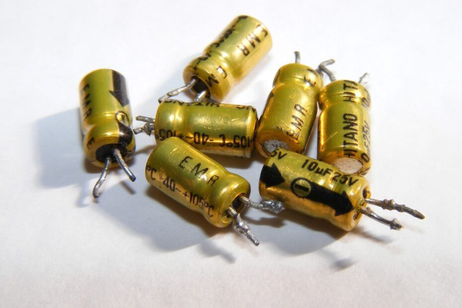
Electrolytic capacitors: These capacitors use an electrolyte solution as the dielectric, and they have a high capacitance value. They are commonly used in circuits that require a large amount of capacitance, such as in power supplies and audio equipment.
Ceramic capacitors: These capacitors use a ceramic material as the dielectric, and they have a low capacitance value. They are commonly used in circuits that require a small amount of capacitance, such as in high-frequency applications.
Tantalum capacitors: These capacitors use a tantalum oxide layer as the dielectric, and they have a moderate capacitance value. They are commonly used in circuits that require a stable and reliable capacitance value, such as in filter circuits.
Film capacitors: These capacitors use a plastic or paper film as the dielectric, and they have a moderate capacitance value. They are commonly used in circuits that require a stable and reliable capacitance value, such as in filter circuits.
Paper-in-oil capacitors: These capacitors use paper and oil as the dielectric, and they have a low to moderate capacitance value. They are commonly used in circuits that require a stable and reliable capacitance value, such as in filter circuits.
Supercapacitors: These capacitors use a high-surface-area electrode material, such as activated carbon, to create a high capacitance value. They are commonly used in circuits that require a high capacitance value and a fast charging and discharging time, such as in energy storage applications.
Variable capacitors: These capacitors use a mechanical mechanism, such as a rotating disk or a sliding plate, to adjust the capacitance value. They are commonly used in circuits that require adjustable capacitance, such as in radio tuning circuits.
Capacitors symbols in circuits
In electronic circuits, capacitors are represented by a symbol that consists of two parallel lines, representing the capacitor’s plates, and a curved line, representing the dielectric material between the plates. The symbol may also include a value and unit of capacitance, as well as a voltage rating and polarity markings, if applicable.
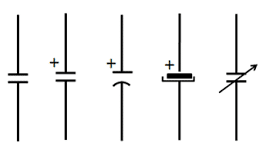
The polarity of the capacitor, if applicable, is indicated by a “+” or “-” symbol on one of the parallel lines.
In some cases, the capacitor symbol may include additional markings or annotations, such as a tolerance rating or a temperature coefficient. These additional markings can provide important information about the capacitor’s performance and characteristics, and they should be considered when selecting a capacitor for a particular circuit.
Overall, the capacitor symbol is a standard and widely recognized way of representing capacitors in electronic circuits. By understanding this symbol and its various components, you can accurately interpret and analyze circuit diagrams that contain capacitors.
How to choose the right capacitor for my circuit?
Once the capacitance has been identified, you also have to pay attention to the following specifications:
- Check for the capacitor’s voltage rating. This is the maximum voltage that the capacitor can safely handle without damaging its internal components.
- Identify the capacitor’s size and shape. Capacitors come in a wide range of sizes and shapes, including cylindrical, rectangular, and circular.
- Look for the capacitor’s tolerance rating. This is the manufacturer’s stated deviation from the capacitance value, typically expressed as a percentage.
- Check for the capacitor’s temperature coefficient. This is the rate at which the capacitor’s capacitance changes with temperature.
- Identify the capacitor’s lead spacing. This is the distance between the leads or terminals of the capacitor, which determines how it can be mounted in a circuit.
- Look for the capacitor’s polarity markings. Some capacitors have a positive and negative terminal, indicated by a “+” or “-” symbol on the capacitor’s body. It is important to connect these terminals correctly in a circuit.